
Robotic Dog

Project Summary
Compact, modular robotic companion for DIY assistance
- ESP32
- MG90s
- 3D-printed chassis
- Gait control
- Wi-Fi remote
- Lightweight
- lasercut tray
- PLA Parts
- Design prototype
- function prototype under construction
- stability vs. weigth
- power supply
- space for parts/partsizes
- Following Function
- IMU stabilisation
Content
- The Idea
- 3D Models
- Walking Gait
- Wiring
- Programming the ESP32
- Assembling
- Parts and Prices
- Planned improvements
The Idea
Dogs are a person’s best friend.
Imagine having one that helps you like a true companion on every DIY project—handing you tools or fetching the parts you need.
Of course, for animal welfare reasons, it wouldn’t be a real dog, but a robotic one.

Functionality
The robotic dog should be able to follow its owner autonomously and carry parts or tools in a tray on its back. Due to a lack of qualified recievers which fit in the skaled dog, the first version will be controlled with a webserver and has no autonomous function.
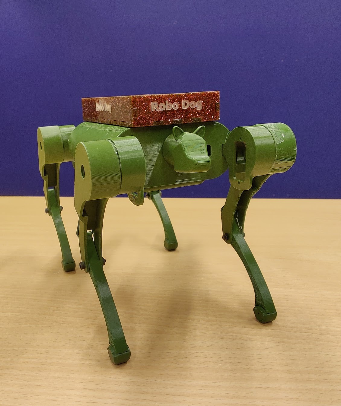
Realistic Prototype
Since strong servos are quite expensive, the prototype was scaled down. The prototype should consist of 3D-printed body parts and 4 legs with 2 degrees of freedom each, driven by servos. The tray on the back should be able to carry small parts and should be detachable.
Control
Even so John Bradnam already provided code for walking gaits, all code was developed from scratch.
The control components differ from the original design, too.
The robotic dog is controlled by an ESP32 and the MG90S servos are controlled via a PCA9685 servo driver board.
Following the owner is realized with the help of two RXB6 recievers which locate a 433 MHz transmitter held by the owner.
3D-Models
The basis for the robotic dog are 3D models from John Bradnam on www.hackster.io. Many changes were nessesary to fit the components which should be used and make the carrying function possible. This is discribed on Noras project site, because she did major part of 3D-Design. All code and the parts are provided in a GitHub respository
Walking Gait
The first version of the robotic dog has no interial measurement unit (IMU) and therefore no feedback control. Hence the walking gait had to be very stable and is only based on time.
Therefore, a walking gait was developed where the robot always has three legs on the ground.
The walking gait is based on four phases. In each phase, one leg is lifted, moved forward and set down again, while the other three legs provide stability.
The following pattern is used:
- left front leg
- right rear leg
- right front leg
- left rear leg
Inverse kinematic
For a smooth walking gait, the servo angles have to be calculated depending on the desired foot position.
Therefore, an inverse kinematic for the legs was developed. Each leg has two degrees of freedom, which are controlled by two servos.
The following figure shows the a model of one leg:
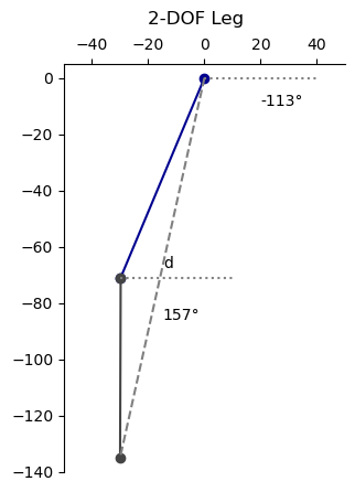
With the cosine law, the angles of the servos can be calculated:
This are the formulas for the inverse kinematic of one leg.
With these formulas, the servo angles can be calculated depending on the desired foot position. So it is possible to define smooth trajectories for the feet during the walking gait.
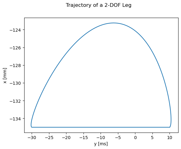
Movement of the legs
With the help of the inverse kinematic, it is possible to define trajectories for a feet in x and y dimension.
There are some requirements for the trajectories during the walking gait:
- The foot has to be lifted during the forward movement.
- The foot has to move smoothly.
- The foot has to be set down smoothly.
- The foot has to be accelarated smoothly.
Where P0 to P4 are the control points of the Bezier curve and t is a parameter between 0 and 1.
The following curve is used for the foot trajectory during the walking gait:
As described above, the walking gait is divided into four phases.
In each phase, one leg is lifted, moved forward and set down again, while the other three legs provide stability.
Feel free to try it out:
Simulation of a leg
Before implementing the walking gait on the real leg, the movement of one leg was simulated in Python.
This made it possible to verify the moments, speeds und positions.
It allowed to optimize the walking gait before implementing it on the real robot.
A maximum weight of 500 g was assumed for the dog which is distributed on three legs on time.
The MG90s servos can provide a stall torque of 0.177 Nm which was divided by three for safety reasons.
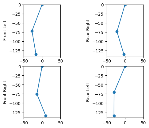
The folowing figure shows the results of the simulation:
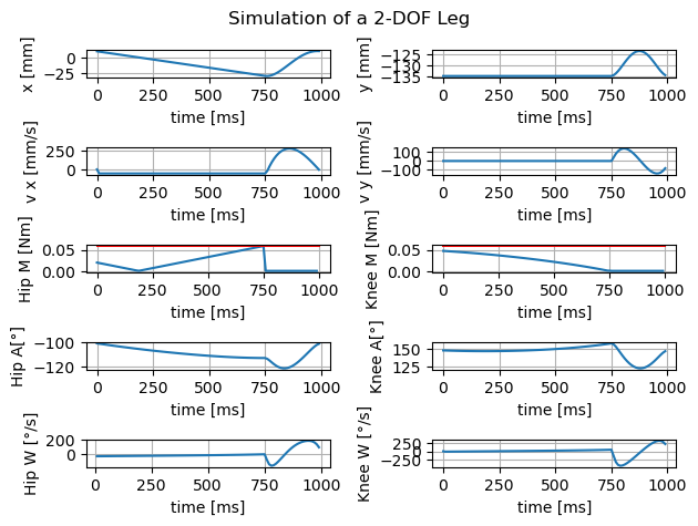
All values are in a safe range for the servos and the variations are continuous and smooth. Therefore, the walking gait can be implemented on the real robot. If the robot will be lighter, even bigger step lengths are possible.
Steering
Since the robot has a 2 DOF leg which can only move in the sagittal plane, steering is limited like on a tracked vehicle.
Steering is realized by different step lengths for the left and right legs.
If the left legs have a bigger step length than the right legs, the robot turns to the right and vice versa.
The bigger the difference between the step lengths, the sharper the turn.
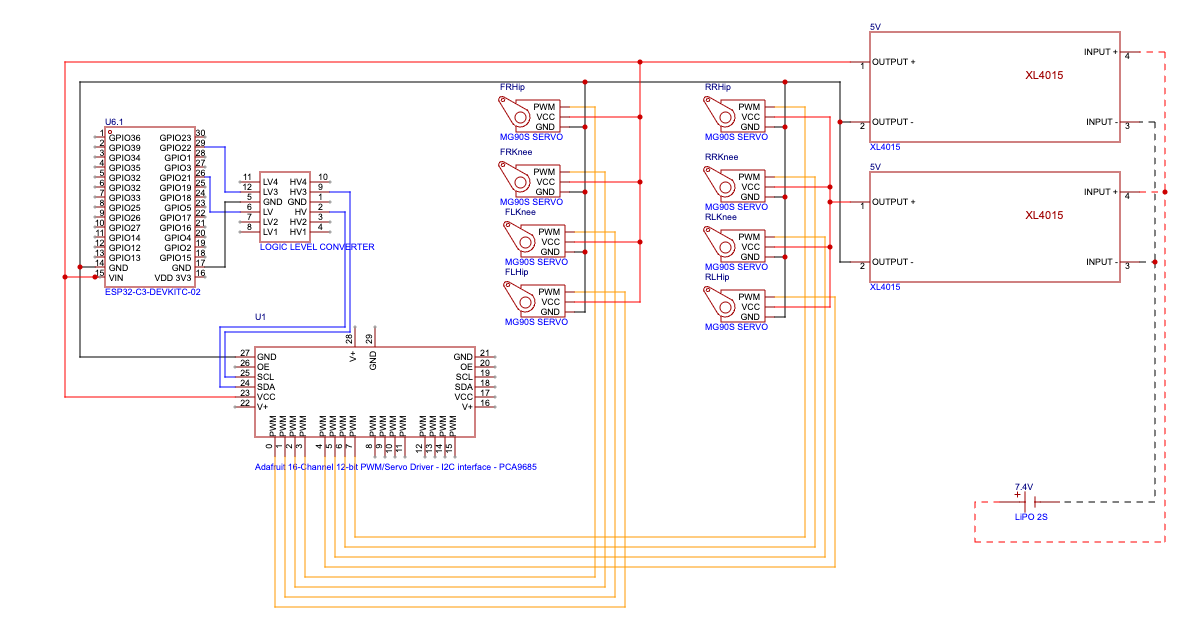
Wiring
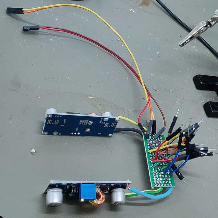
As already mentioned, the robotic dog is controlled by an ESP32 and the MG90S servos are controlled via a PCA9685 servo driver board.
In addition, a 7,4 V 2000 mAh 15C LiPo battery and two XL4015 are used to supply the robot dog with sufficent power.
The XL4015 convert the battery voltage to 5 V. The servos are connected directly to the XL4015 outputs, four to each.
The ESP32 and the PCA9685 are also supplied with 5 V from the XL4015 and are interconnected with I2C.
The folowing schematic shows the wiring of the components:
Programming the ESP32
The ESP32 was programmed with ESP-IDF in a combination of C and C++ in VS Code. There are two classes one for the I2C-bus and one for a leg. They are capsuled in wrappers to be useable in the main programm which is written in C. Since all code is avaiable on GitHub
The class Leg includes the trajectories and the inverse kinematic and allows to build four objects of type Leg which have its own step height, step length and height, but use a step time together.
Debugging
For testing the software and for debugging, there is debug.c file which defines functions for usb output. The usb output can be visualized with a python script that animate the legs in time.
As the following picture shows:
Web interface
Since the "Follow Owner"-function isn't implemented yet, the robot is fully controlled with the webinterface.
The ESP32 creates an accespoint which SSID and passwort must be defined in ESP-IDF.
When connected, the server is on http://192.168.4.1 and looks like shown below.
Feel free to try it yourself: Here
Assembling
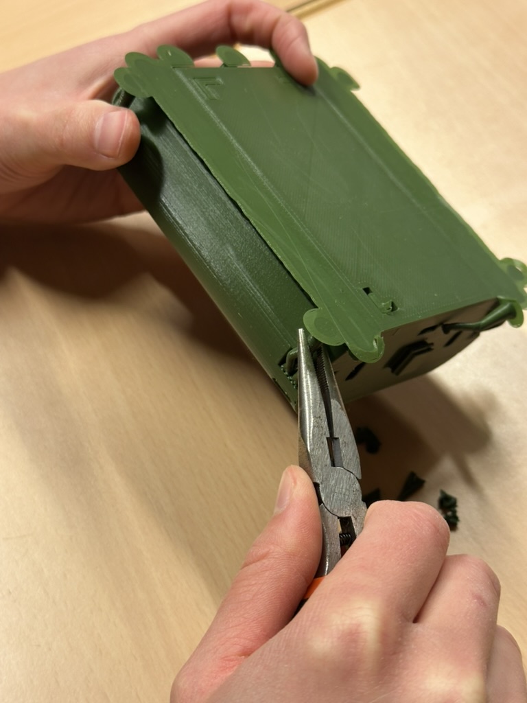
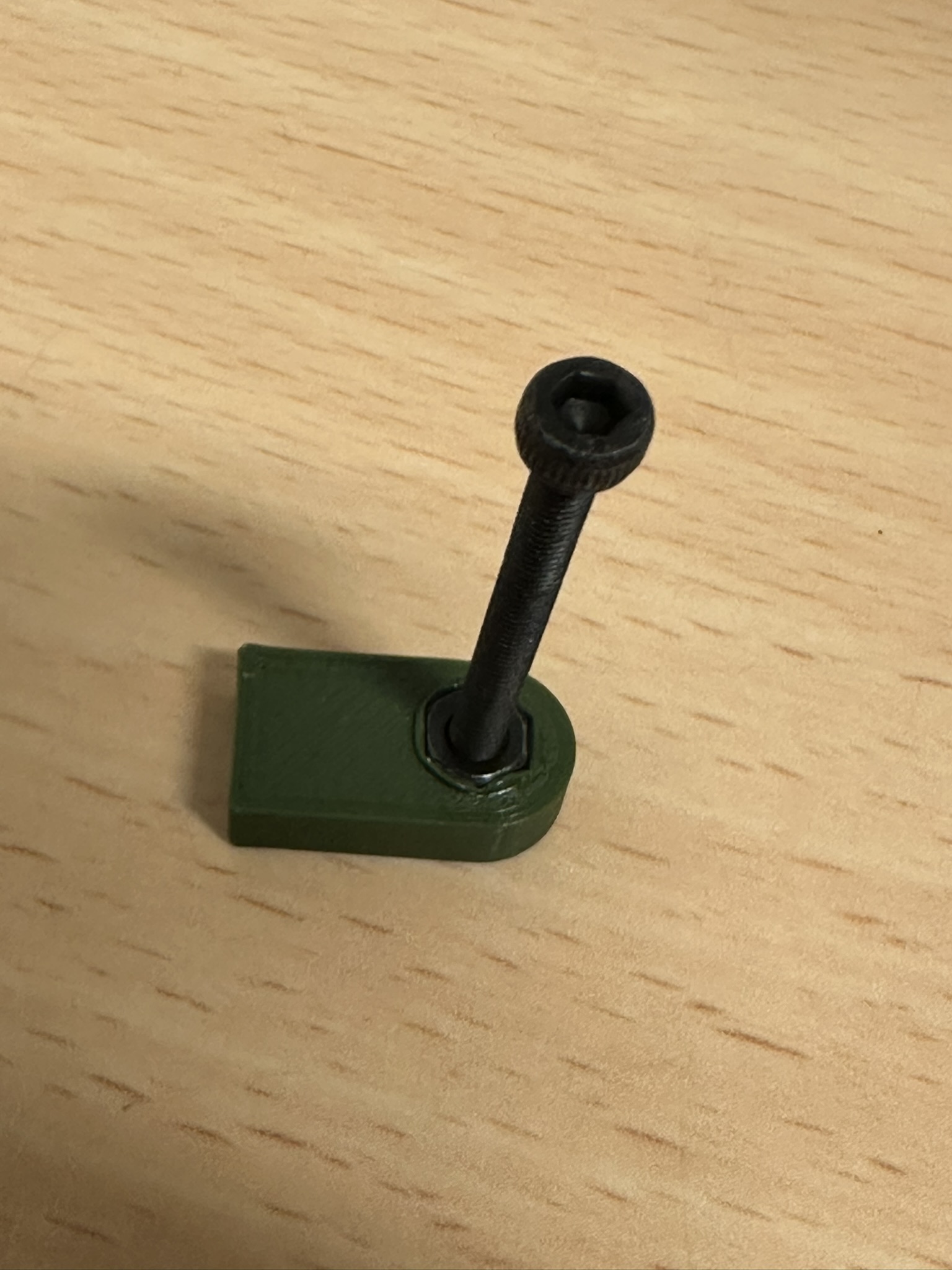
Post treatment of 3D printed parts
Once the print is finished, the parts looks as shown in the picture below.

Therefore, pliers and a sharp knife are useful.
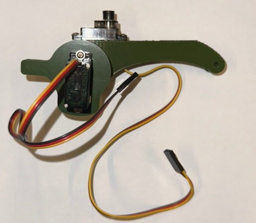
Build a leg
Before assembling the leg, all servos should be in a defined state, so that there are no surprises when the robot starts moving. It is recommanded to use the calibration web interface and set all angles to 90 degrees.
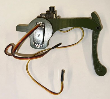
First, the hip servo is screwed to the hip element. Then, the thigh is set on the gearwheel of the servo is screwed tight. There are different parts for left and right, so it is important to use the right ones. In the next step, the knee servo is screwed to the tight.
The following picture shows the current state.
Wiring and solding
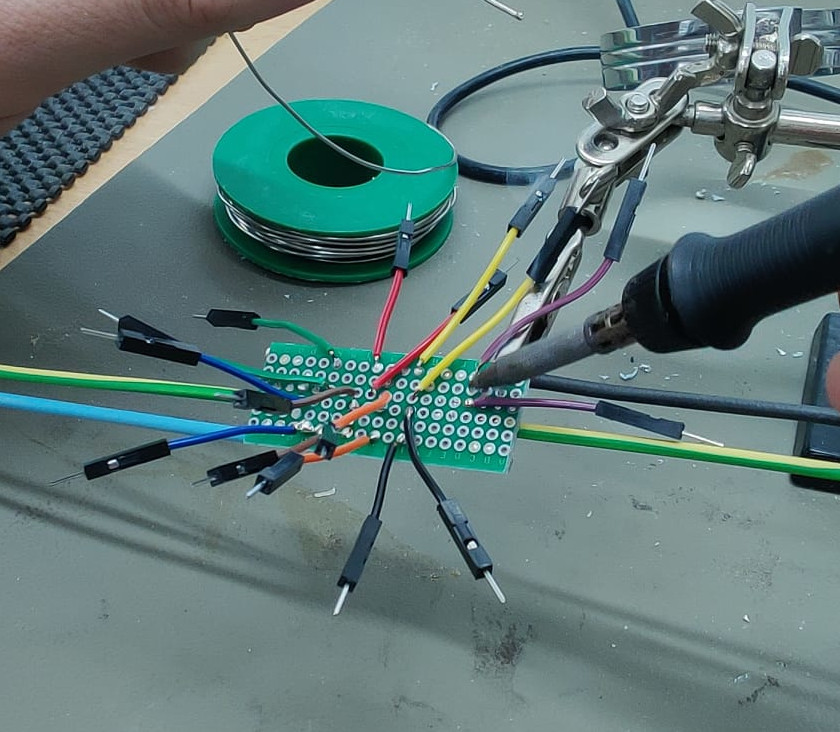
Most cables are connected via soldering, because it needs less space than other methods.
First step is the design of the perforated board which is used to distribute the current from the two XL4015.
As shown in the part Wiring, there is only one ground for all components which is important for the interpretation of the i2c and pwm signal.
One XL4015 5 V is only connected to four servos and the other is connected to four servos and the ESP32 and the PCA9685.
Due to a defect of the level shifter, the shown dog uses only 3.3V for the PCA9685 from the ESP32. Check if the used servos work with 3.3V pwm signals.
Short jumper male ends can be used as connection between the board and the servos. The ESP32 (and PCA9685) is connected wie male-female jumper wires which are soldered to the board, too.
The body
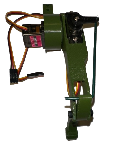
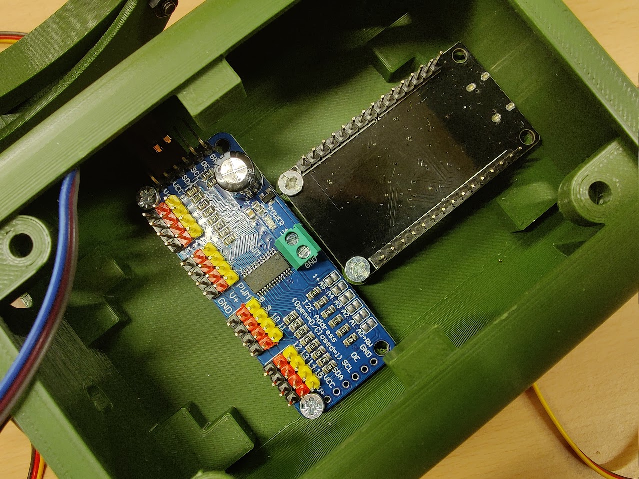
Before assembling the body, the electronic components should be placed in the body parts as shown below.
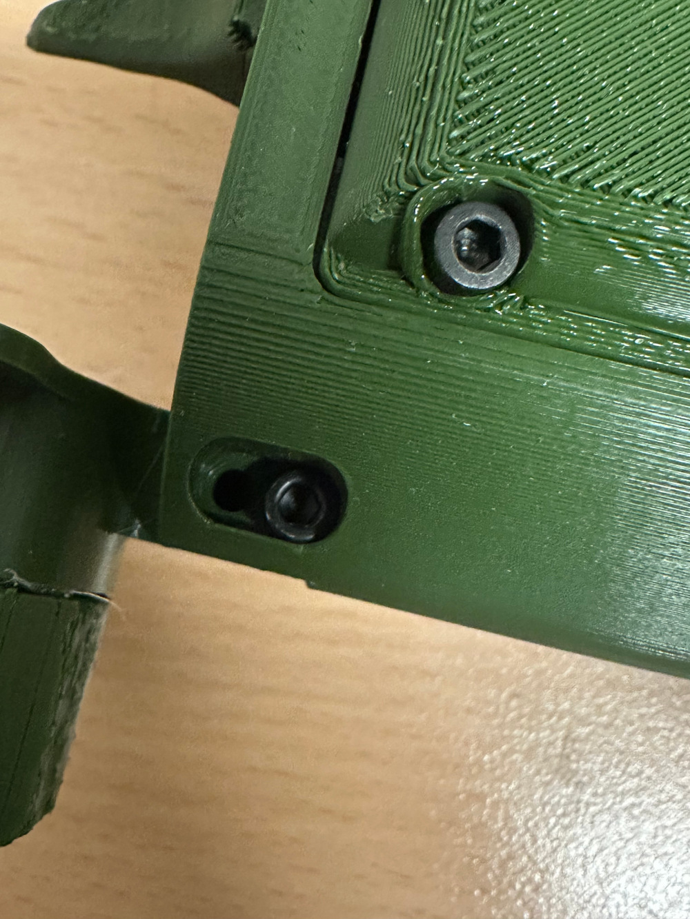
The following two pictures show the assembled design model from different perspectives.
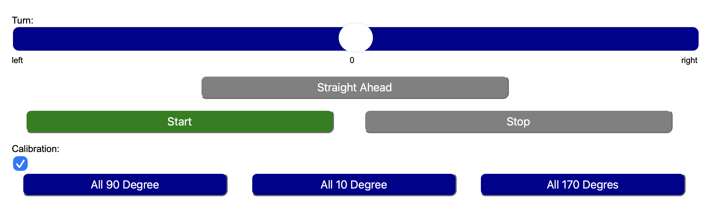
Calibration
Before starting the servos, the parameters of the servo must be compared to the cal.h, otherwise the servos could be destroyed.
For the best result, the robot has to be calibrated. In this version, a complete calibration with the webserver isn't possible.
When the robot and the software is set up, the "All 90 Degree","All 10 Degree","All 170 Degree" buttons can be used for calibrating.
If the results are not satisfying, the pwm values in the cal.h can be changed to improve the precision.
The formula for calibration is:
Parts and Prices
| Amount | Part | Price |
|---|---|---|
| 1 | ESP32 | 6.99 €1 |
| 1 | PCA9685 | 6.89 € |
| 8 | MG90S | 19.99 € |
| 2 | XL4015 | 5.33 €1 |
| 1 | 7,4 V Li-ion 2000mAh | 16.98 € |
| 1 | perforated board | 0.55 €1 |
| small amount | solder | 3.99 €2 |
| 1 Set | Jumper Wires | 6.99 €2 |
| 1 Set | M3 Screws | 6.99 €2 |
| 300g | PLA filament | 6.90 €1 |
| 26g | silicone SH A 45 | 7.95 € |
| 200 cm2 | acrylic glas (PMMA) | 10.20 €2 |
| 8 | Nail 0.9 x 30 mm | 0.25 €1 |
| small amount | talc powder | 2.59 €2 |
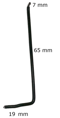
| 40cm | 1.8 mm plastic coated iron wire | 3.60 €2 |
| Total | 97.19 € |
2 can't be calculated, so hole set price
Machines and Tools
- Trotec laser
- Prusa MK4S
- soldering station
- multimeter
Planned improvements
- real size
- following function
- stabilisation
- improved calibration
- different walking gaits
This project was a cooperation with Nora. Please check her website, too.
License
Since the originals are licenced under GPL3+, this project is also licenced under GPL3+.