Compulsory Elective Course Production Engineering
This isn't a real project. The Compulsory Elective Course Production Engineering is described here which was a requirement for the grading.
Content
Web Development
The basic set up of Visual Studio Code for web development was taught. Then the structure of html and the most common tags were explained and it was shown that CSS and JavaScript make website much prettier and more powerfull.
In the end, everybody was able to upload a website to github and published it.
Here are the links to the other websites which were made in this course.
Not only this website is part of it, a nice, small and illustrative example can be found in the robotic dog project, which is described in more detail here.
-
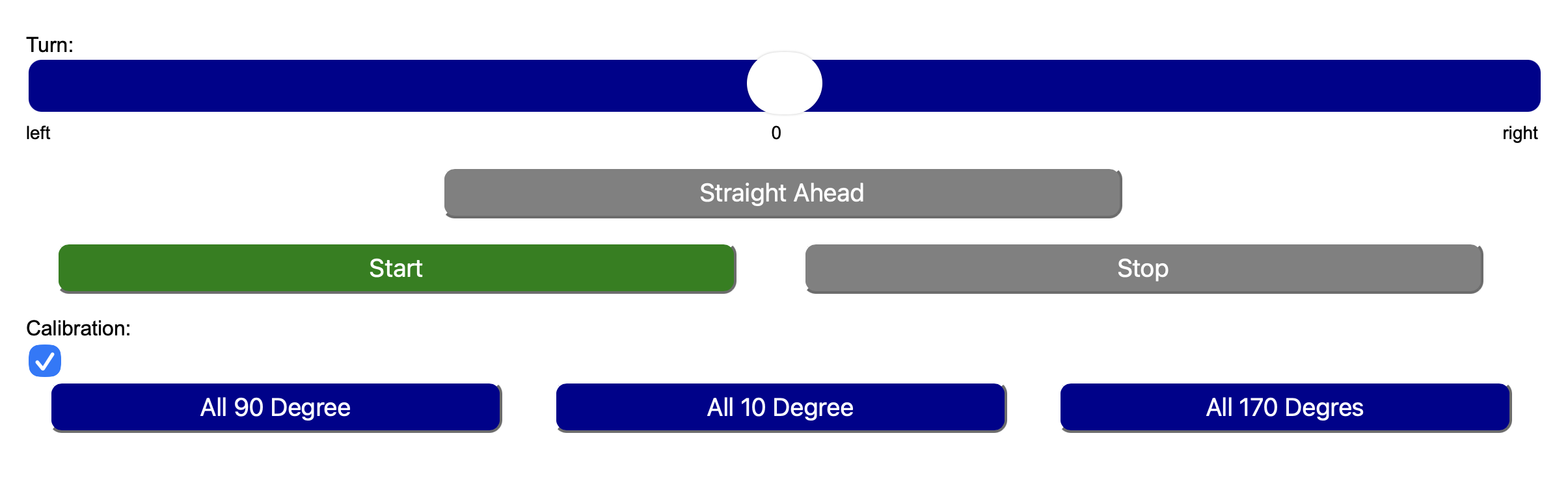
a slider, like:
                                    <label for="turn">Turn:</label><br>

<input type="range" class="slider" id="turn" min="-10" max="10" value="0" oninput="turn(this.value)"> -
buttons, like:
<button id="bStart" class="startstop activeStart" onclick="start()">Start</button> -
a checkbox, like:
<input id="cal" type="checkbox" onclick="calStart()"><br> -
css styles, like:
                                    .startstop{

                                          width:45%;

                                          height:40px;

                                          margin-left:2%;

                                          margin-right:2%;

                                          font-size:larger;

                                          color:white;

border-radius: 10px;} -
javascript functions, like:
                                    function start() {

                                          fetch(`/go`)

                                                .then(response => response.text())

                                                .then(data => console.log(data))

                                                .catch(err => console.error(err));


                                          s = document.getElementById("bStart");

                                          s.classList.remove("activeStart");

                                          s.classList.add("inactive");


                                          s = document.getElementById("bStop");

                                          s.classList.add("activeStop");

                                          s.classList.remove("inactive");}
Feel free to try it yourself: Here is the result.
3D CAD and 3D Printing
Learning how to use Fusion for 3D design, followed by slicing and finally 3D printing, is a step-by-step process that combines creativity, technical skills, and practical problem-solving. The workflow typically begins with understanding the basic tools and interface of Fusion, then progresses to creating increasingly complex models.
1. Learning Fusion (CAD Modeling)
The first stage is becoming familiar with Fusion’s user interface and modeling tools.
This includes sketching basic shapes, using constraints and dimensions, and learning how
to extrude, cut, and modify geometry. Then there were some more advanced techniques like fillets.
The goal is to learn how to model objects precisely so they can be manufactured or printed successfully.
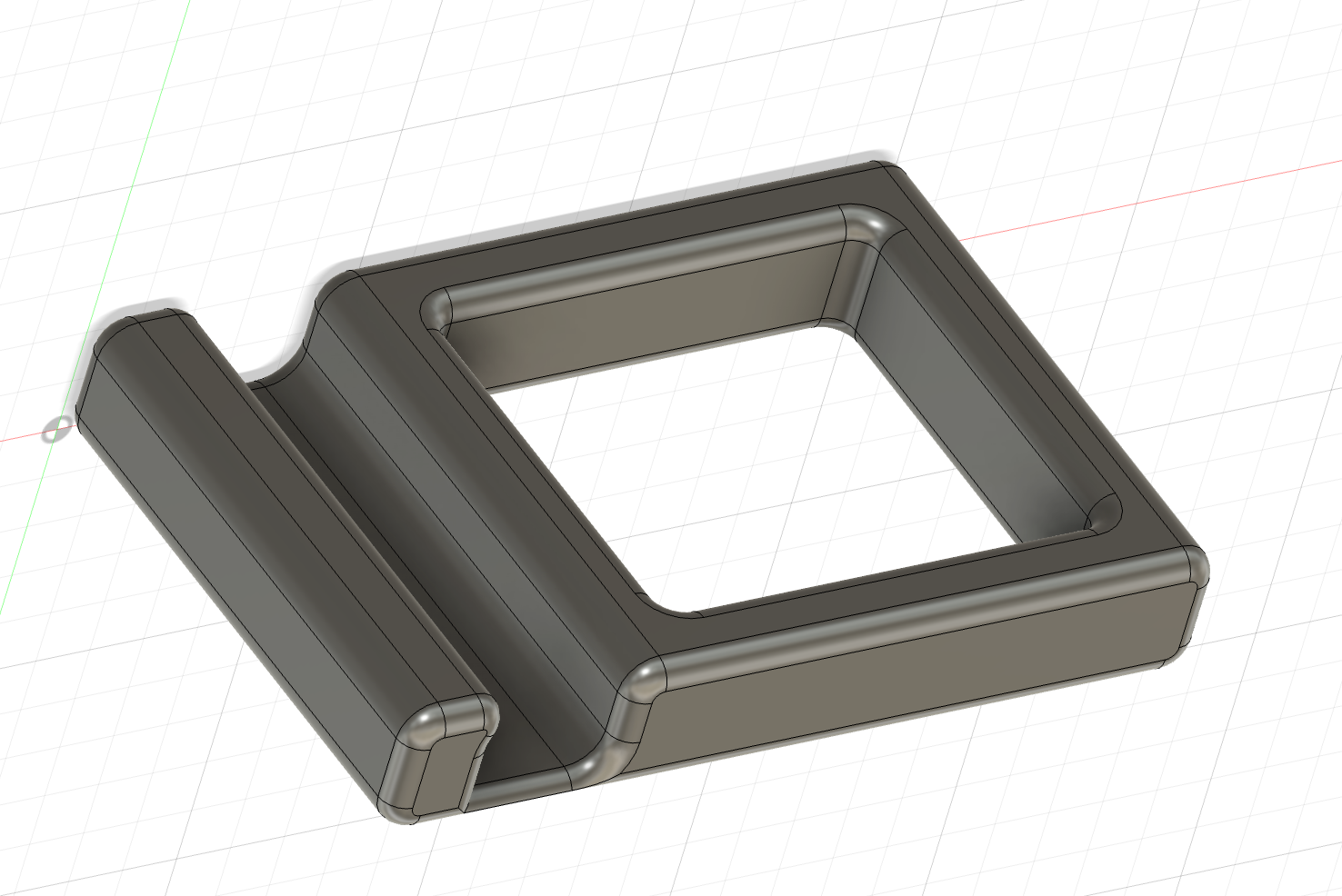
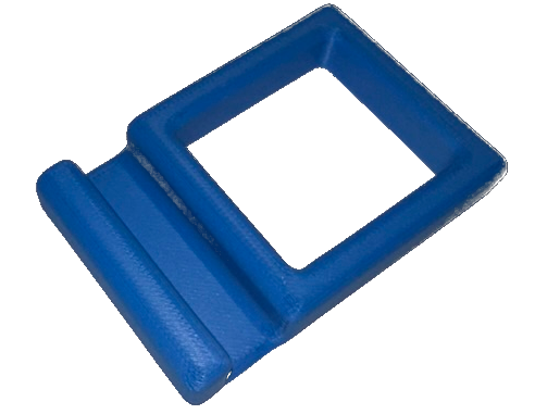
In this course, a mobile phone mount was desgined. The 3D model in Fusion is shown below.
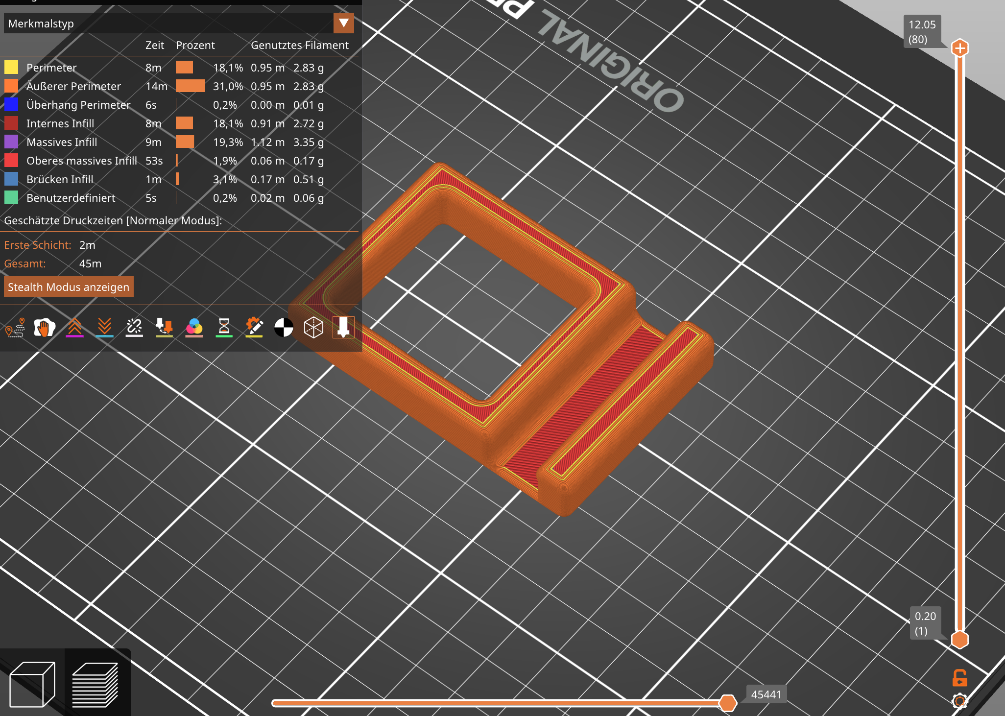
2. Exporting and Slicing
Once the model is complete, it is exported as an STL file. This file is then opened
in PrusaSlicer. In the slicer, it is possible to prepare the
model for 3D printing by adjusting layer height, infill density, supports, temperatures,
speeds, and other printing parameters. The slicer converts the model into G-code, which
contains all the instructions the printer needs to build the object.
Here is a sliced version of the mobile phone mount.
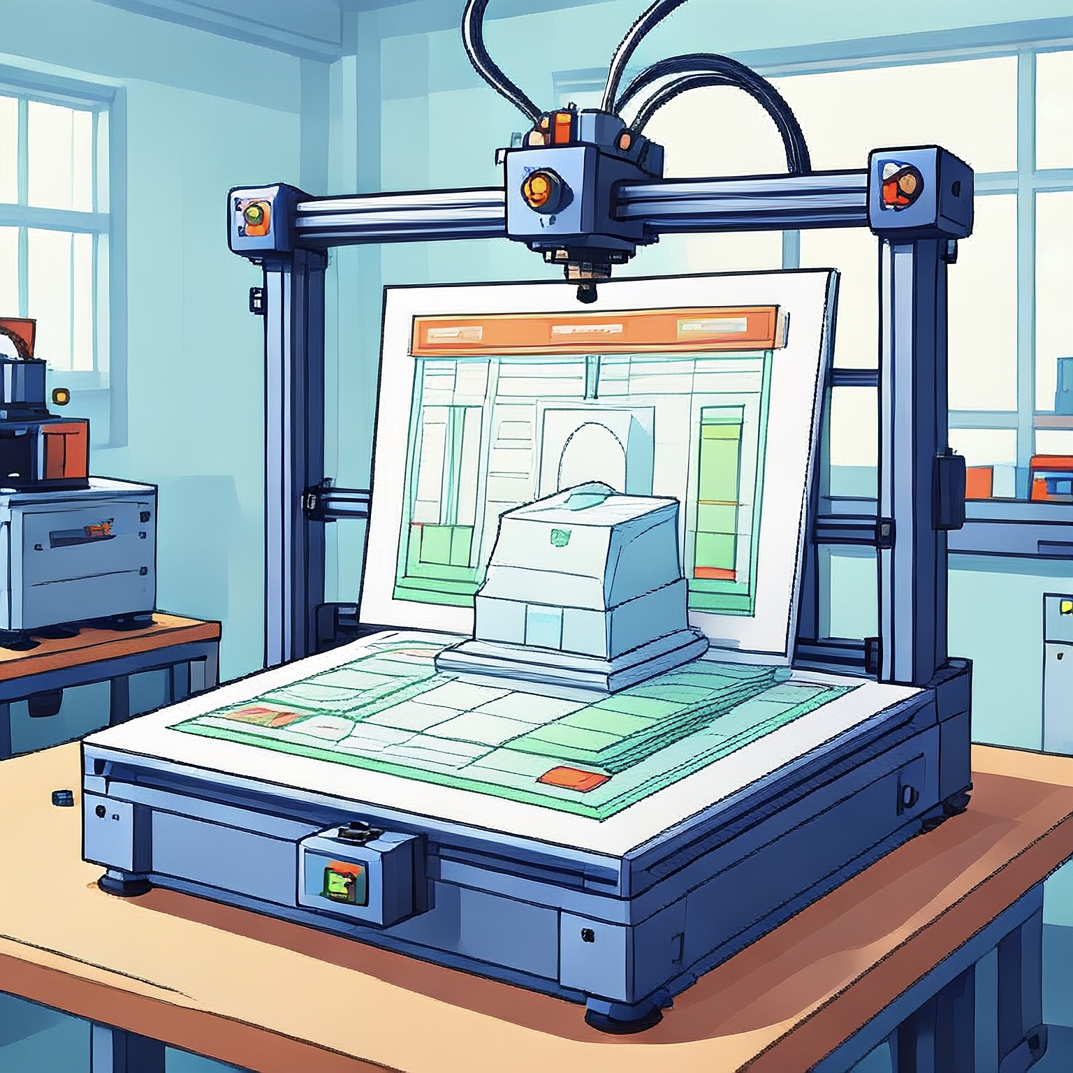
3. 3D Printing
The final step is sending the G-code to the 3D printer and preparing the printer by preheating,
loading the filament and ensuring that the build plate is properly leveled and clean. After starting
the print, the machine follows the G-code instructions layer by layer. Once printing is
complete, the finished part is removed from the build plate, cleaned from supports, and inspected.
This is the real 3D- printed mobile phone mount which was built from skratch in a few hours.
For more about the post treatment of 3D-printed parts, check the robotic dog project.
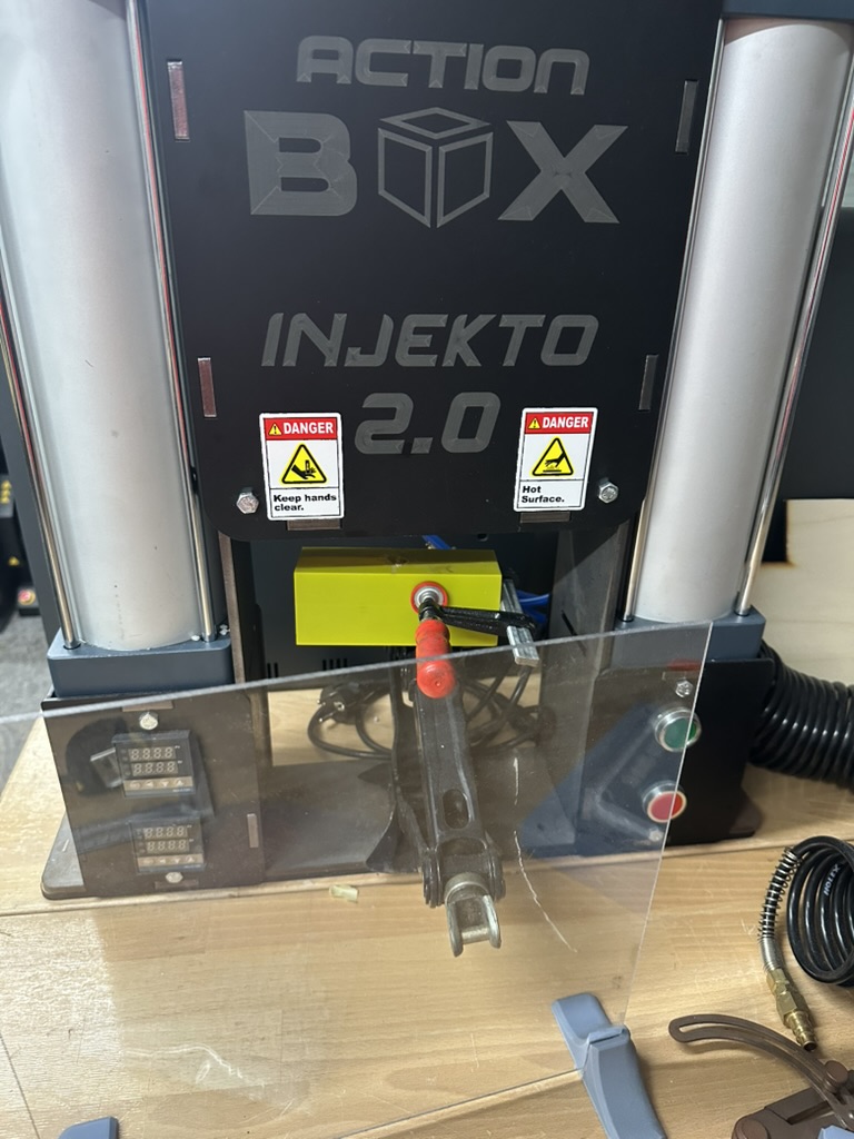
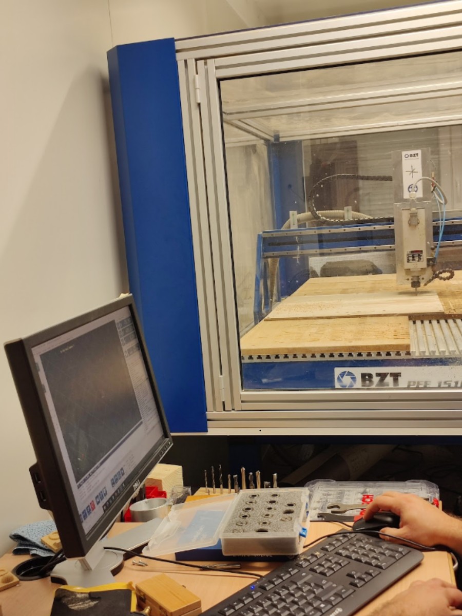
CNC Milling, Injection Molding, and Lathe
The basics of CNC milling and G-code were introduced.
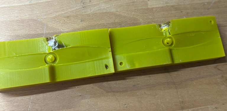
Since the 3D-printed mold had already been used several times, the resulting injection molded parts were of poor quality.
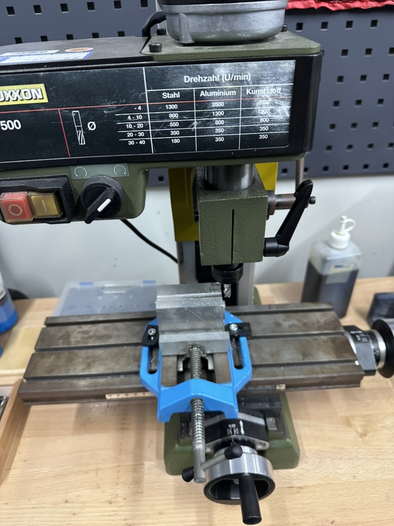
On the conventional milling machine and the lathe, there was much more to learn and try out. After reading and understanding all safety instructions, the first task was to mill a groove into an aluminium block.
The most important aspect here is to turn the adjustment wheel slowly and smoothly in order to achieve a clean surface and avoid damaging the cutter.
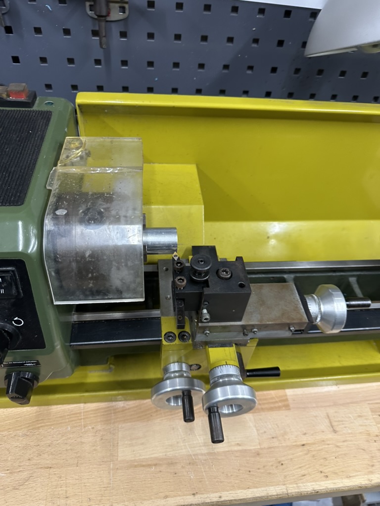
After locating and replacing a blown fuse on the lathe, the next exercise was to machine an M10 thread onto a 20 mm brass shaft. Again, a slow and precise hand movement is crucial; otherwise the indexable insert can break — which is not only inconvenient but also quite loud.
After reducing the diameter to 10 mm and adding a chamfer, cutting the thread with the thread cutter should have been straightforward, but in this case it was not. In the end, it was impossible to hold the thread cutter firmly enough, even after further reducing the diameter and enlarging the chamfer.
Here are some expressions of the mashines:
Laser
The introduction to laser cutting covered both the basic safety rules and the complete workflow from creating a vector design to the final cut.
Before using the machine, the first step was to design the parts in a vector graphics program such as Inkscape. Here it is essential to choose the correct line styles: hairline for cutting andat least 0.5 mm line width for engraving. Otherwise to much material is burnt oder the engraving is not readable.
Furthermore, the colors have to be correct: red for cutting and black for engraving. This ensures that the laser cutter software correctly distinguishes between cut paths and engraved areas.
After a short explanation of how the laser operates and which materials can (and cannot) be processed, the vector file was imported into the laser cutter software. Power, speed, and number of passes had to be set carefully depending on the material and thickness.
The most important point here is to select the correct settings for the material. Too much power can burn or char the edges, while too little power prevents the cut from going through — resulting in a part that needs to be recut.
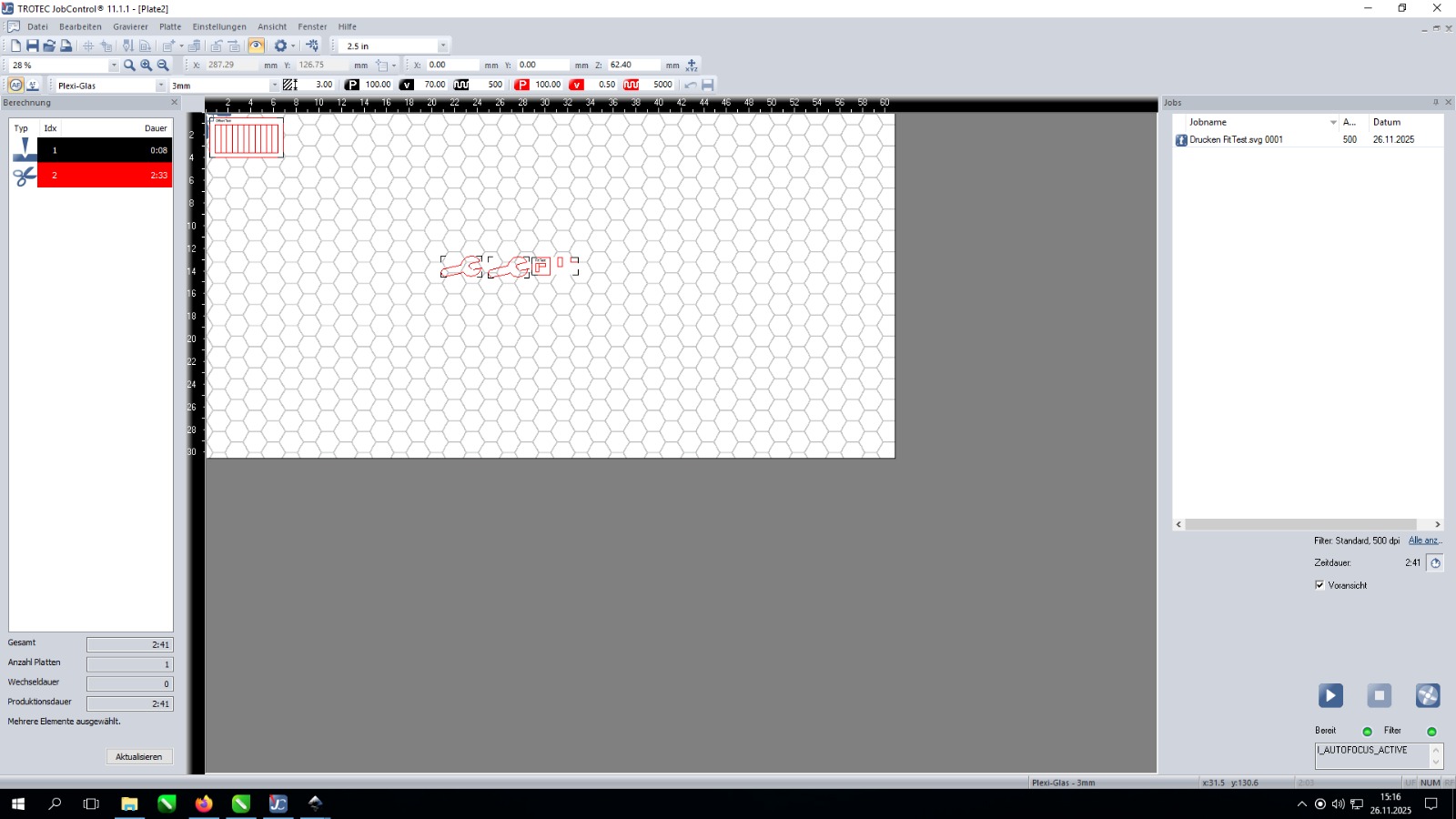
The following image shows the interface of the laser cutting software.
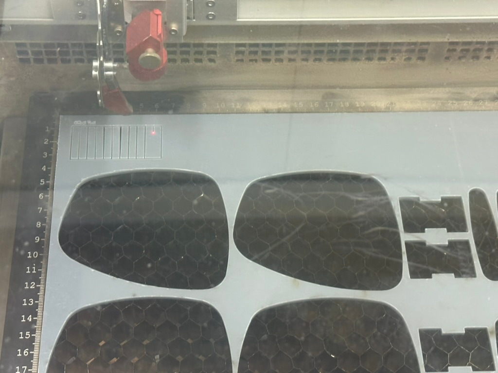
The following picture shows the working laser. The red laser dot is only for configuration and the cutting laser is invisible.
Overall, laser cutting turned out to be one of the fastest and most satisfying manufacturing methods, especially for rapid prototyping, creating simple mechanical parts, and producing custom shapes directly from digital designs.
For more about laser cutting, check the walking robot project.